- Front-Panel LEDs
- Front-Panel LEDs
- Removing the Air Duct
- Installing the Air Duct
- Required Equipment For Service Procedures
- Shutting Down and Removing Power From the Server
- Shutting Down Using the Power Button
- Shutting Down Using The Cisco IMC CLI
- Shutting Down Using The Cisco IMC GUI
- Serviceable Component Locations
- Replacing SAS/SATA Hard Drives or Solid-State Drives
- SAS/SATA Drive Population Guidelines
- Replacing a SAS/SATA Drive
- Basic Troubleshooting: Reseating a SAS/SATA Drive
- Reseating a SAS/SATA Drive
- Front-Loading NVMe SSD Population Guidelines
- Front-Loading NVME SSD Requirements and Restrictions
- Replacing a Front-Loading NVMe SSD
- Installing a PCIe Cable For Front-Loading NVMe SSDs
- Required Equipment for Replacing Riser Cages
- PCIe Riser Options
- Replacing the Same Riser Types
- Removing Half Height Riser Cages
- Installing Half Height Riser Cages
- Removing Full Height Riser Cages
- Installing Full Height Riser Cages
- Removing Half Height Riser Cages
- Installing Full Height Riser Cages
- Removing Full Height Riser Cages
- Installing Half Height Riser Cages
- CPU Configuration Rules
- Tools Required For CPU Replacement
- Removing CPUs and Heat Sinks
- Installing the CPUs and Heatsinks
- Additional CPU-Related Parts to Order with RMA Replacement CPUs
- DIMM Population Rules and Memory Performance Guidelines
- Replacing DIMMs
- Replacing AC Power Supplies
- Replacing DC Power Supplies
- Installing DC Power Supplies (First Time Installation)
- Grounding for DC Power Supplies
- Removing an mLOM Card (2FH Riser Cages)
- Installing an mLOM Card (2FH Riser Cages)
- Removing an mLOM Card (3HH Riser Cages)
- Installing an mLOM Card (3HH Riser Cages)
- Cisco VIC mLOM and OCP Card Replacement Considerations
- Removing an OCP Card, 2FH Riser Cages
- Installing an OCP Card, 2FH Riser Cages
- Removing an OCP Card, 3HH Riser Cages
- Installing an OCP Card, 3 HH Riser Cages
- Storage Controller Card Firmware Compatibility
- Replacing a SAS Storage Controller Card (RAID or HBA)
- Cisco Boot-Optimized M.2 RAID Controller Considerations
- Replacing a Cisco Boot-Optimized M.2 RAID Controller
- TPM Considerations
- Installing and Enabling a TPM
- Installing TPM Hardware
- Enabling the TPM in the BIOS
- Enabling the Intel TXT Feature in the BIOS
- Using the Clear CMOS Switch (SW4, Switch 9)
- Using the Clear BIOS Password Switch (SW4, Switch 6)
- Using the Boot Alternate Cisco IMC Image Header (CN5, Pins 1-2)
Servicing the Server
This chapter contains the following topics:
Status LEDs and Buttons
This section contains information for interpreting front, rear, and internal LED states.
Front-Panel LEDs
Front-Panel LEDs
The following illustration shows the LEDs on the server's front panel.

LED Name
States
1

Power button/LED ()
- Off—There is no AC power to the server.
- Amber—The server is in standby power mode. Power is supplied only to the Cisco IMC and some motherboard functions.
- Green—The server is in main power mode. Power is supplied to all server components.
2

Unit identification (
- Off—The unit identification function is not in use.
- Blue, blinking—The unit identification function is activated.
3

System health ()
- Green—The server is running in normal operating condition.
- Green, blinking—The server is performing system initialization and memory check.
- Amber, steady—The server is in a degraded operational state (minor fault). For example:
- Power supply redundancy is lost.
- CPUs are mismatched.
- At least one CPU is faulty.
- At least one DIMM is faulty.
- At least one drive in a RAID configuration failed.
4

Power supply status ()
- Green—All power supplies are operating normally.
- Amber, steady—One or more power supplies are in a degraded operational state.
- Amber, blinking—One or more power supplies are in a critical fault state.
5

Fan status ()
- Green—All fan modules are operating properly.
- Amber, blinking—One or more fan modules breached the non-recoverable threshold.
6

Network link activity ()
- Off—The Ethernet LOM port link is idle.
- Green—One or more Ethernet LOM ports are link-active, but there is no activity.
- Green, blinking—One or more Ethernet LOM ports are link-active, with activity.
7

Temperature status ()
- Green—The server is operating at normal temperature.
- Amber, steady—One or more temperature sensors breached the critical threshold.
- Amber, blinking—One or more temperature sensors breached the non-recoverable threshold.
Rear-Panel LEDs

1
Fan module fault LEDs (one behind each fan connector on the motherboard)
- Amber—Fan has a fault or is not fully seated.
- Green—Fan is OK.
3
DIMM fault LEDs (one behind each DIMM socket on the motherboard)
These LEDs operate only when the server is in standby power mode.
- Amber—DIMM has a fault.
- Off—DIMM is OK.
2
CPU fault LEDs (one behind each CPU socket on the motherboard).
These LEDs operate only when the server is in standby power mode.
- Amber—CPU has a fault.
- Off—CPU is OK.
Serial Number Location
The serial number for the server is printed on a label on the top of the server, near the front. See Removing Top Cover.
Hot Swap vs Hot Plug
Some components can be removed and replaced without shutting down and removing power from the server. This type of replacement has two varieties: hot-swap and hot-plug.
- Hot-swap replacement—You do not have to shut down the component in the software or operating system. This applies to the following components:
- SAS/SATA hard drives
- SAS/SATA solid state drives
- Cooling fan modules
- Power supplies (when redundant as 1+1)
- NVMe PCIe solid state drives
Removing Top Cover
Procedure
Remove the top cover:
- If the cover latch is locked, slide the lock sideways to unlock it. When the latch is unlocked, the handle pops up so that you can grasp it.
- Lift on the end of the latch so that it pivots vertically to 90 degrees.
- Simultaneously, slide the cover back and lift the top cover straight up from the server and set it aside.
Replace the top cover:
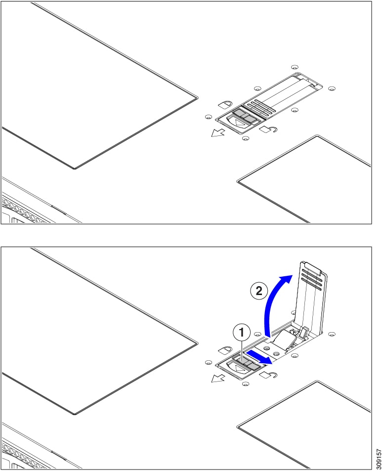
- With the latch in the fully open position, place the cover on top of the server a few inches behind the lip of the front cover panel.
- Slide the cover forward until the latch makes contact.
- Press the latch down to the closed position. The cover is pushed forward to the closed position as you push down the latch.
- Lock the latch by sliding the lock button to sideways to the left. Locking the latch ensures that the server latch handle does not protrude when you install the blade.
1
2
Cover latch handle
Replacing the Air Duct
The server has an air duct under the top sheet metal cover. The air duct ensures proper cooling and air flow across the server from intake (the cool aisle of the data center) to exhaust (the hot aisle in the data center). The air duct is in the middle of the server and covers the CPU and DIMMs.
Two versions of air duct exist for the server.
- For servers with Intel Xeon Fourth Generation Scalable Processors, the existing air duct can be used.
- For servers that have Intel Xeon Fifth Generation Scalable Processors, a new air duct is required (UCSC-AD-C220M7=). For new Intel Fifth Generation servers, the new air duct is preinstalled. For existing Intel Fourth Generation servers that will upgrade to Intel Fifth Generation Xeon Processors, you will need to purchase the new air duct and install it after the CPUs are upgraded. The new air duct is available from Cisco. The identifiable difference between the two air ducts is the different dimensions of the ventilation holes. Compare the following illustrations.


If you remove the air duct , make sure to use the install the correct one.
To replace the server's air duct, use the following procedures:
- Removing the Air Duct
- Installing the Air Duct
Removing the Air Duct
Use this procedure to remove the air duct when needed.
Procedure
Remove the server top cover.
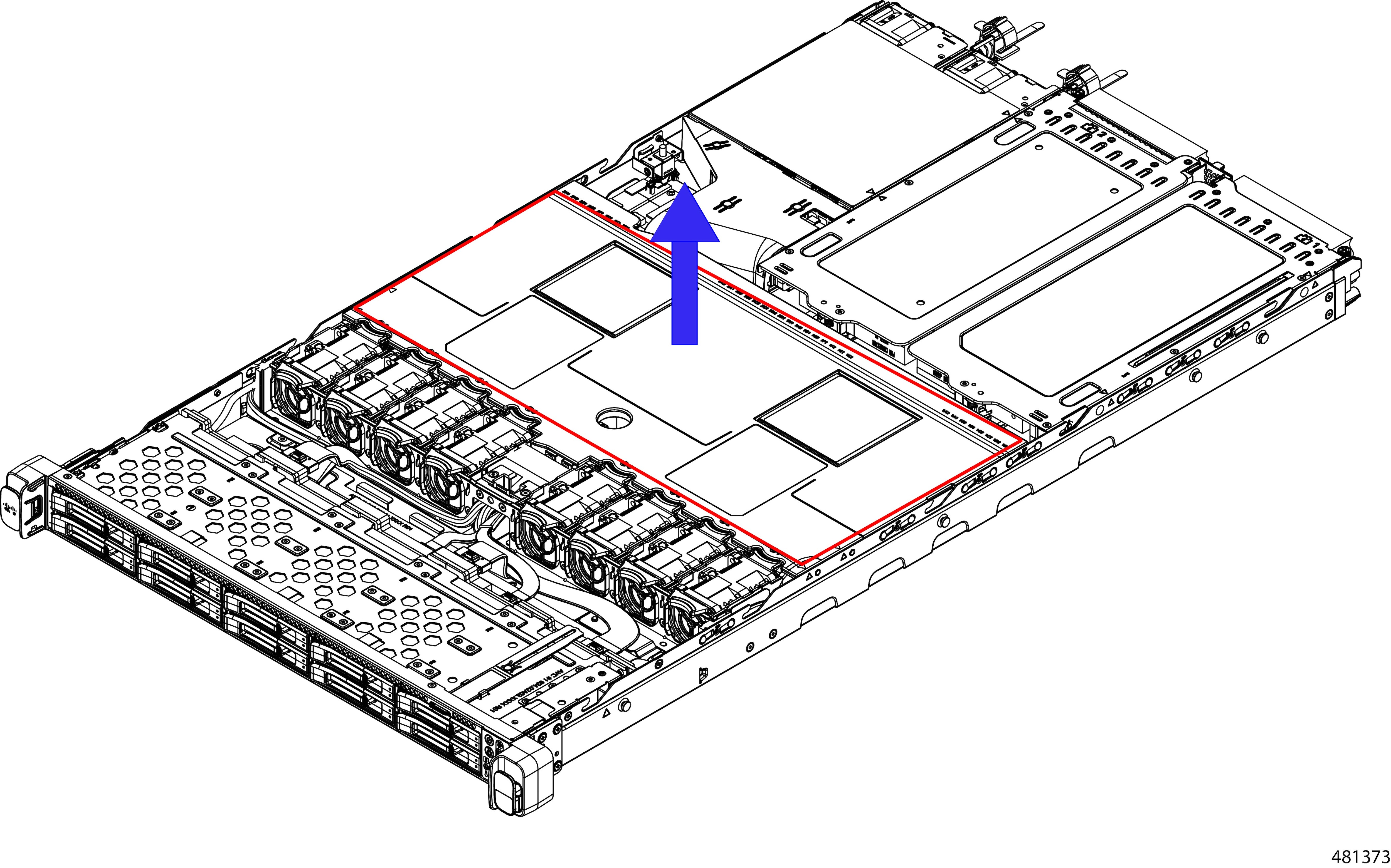
Insert your finger in the finger hole and grasp the air duct.
Lift the air duct off of the server.
You might need to slide the air duct towards the front or back of the server while lifting the air duct up.
What to do next
When you are done servicing the server, install the air duct. See Installing the Air Duct.
Installing the Air Duct
The air duct sits behind the front-loading drive cage and covers the CPU and DIMMs in the middle of the server.
The existing airflow baffle and the new airflow baffle (UCSC-AD-C220M7=) are similar enough that you can use this procedure for both.
Procedure
Orient the air duct.
Install the air duct.
- Align the detents and alignment features on the air duct with the alignment features on the chassis wall.
- Holding the air duct level, lower it onto the chassis, making sure that the detents match with their receiving parts on the chassis sheetmetal walls.
- When the air duct is correctly positioned, gently press down to ensure that all of its edges sit flush.
If the air duct is not seated correctly, it can obstruct installing the server's top cover.
For the existing air duct, install it as shown.
When the air duct is correctly seated, attach the server's top cover.
The server top cover should sit flush so that the metal tabs on the top cover match the indents in the top edges of the air duct.
Preparing For Component Installation
This section includes information and tasks that help prepare the server for component installation.
Required Equipment For Service Procedures
The following tools and equipment are used to perform the procedures in this chapter:
- T-30 Torx driver (supplied with replacement CPUs for heatsink removal)
- #1 flat-head screwdriver (supplied with replacement CPUs for heatsink removal)
- #1 Phillips-head screwdriver (for M.2 SSD and intrusion switch replacement)
- Electrostatic discharge (ESD) strap or other grounding equipment such as a grounded mat
Shutting Down and Removing Power From the Server
The server can run in either of two power modes:
- Main power mode—Power is supplied to all server components and any operating system on your drives can run.
- Standby power mode—Power is supplied only to the service processor and certain components. It is safe for the operating system and data to remove power cords from the server in this mode.
After a server is shut down to standby power, electric current is still present in the server. To completely remove power as directed in some service procedures, you must disconnect all power cords from all power supplies in the server.
You can shut down the server by using the front-panel power button or the software management interfaces.
Shutting Down Using the Power Button
Procedure
Check the color of the Power button/LED:
- Amber—The server is already in standby mode, and you can safely remove power.
- Green—The server is in main power mode and must be shut down before you can safely remove power.
Invoke either a graceful shutdown or a hard shutdown:
- Graceful shutdown—Press and release the Power button. The operating system performs a graceful shutdown, and the server goes to standby mode, which is indicated by an amber Power button/LED.
- Emergency shutdown—Press and hold the Power button for 4 seconds to force the main power off and immediately enter standby mode.
If a service procedure instructs you to completely remove power from the server, disconnect all power cords from the power supplies in the server.
Shutting Down Using The Cisco IMC CLI
You must log in with user or admin privileges to perform this task.
Procedure
At the server prompt, enter:
Example:
At the chassis prompt, enter:
Example:
server/chassis# power shutdownThe operating system performs a graceful shutdown, and the server goes to standby mode, which is indicated by an amber Power button/LED.
If a service procedure instructs you to completely remove power from the server, disconnect all power cords from the power supplies in the server.
Shutting Down Using The Cisco IMC GUI
You must log in with user or admin privileges to perform this task.
Procedure
In the Navigation pane, click the Server tab.
On the Server tab, click Summary.
In the Actions area, click Power Off Server.
Click OK.
The operating system performs a graceful shutdown, and the server goes to standby mode, which is indicated by an amber Power button/LED.
If a service procedure instructs you to completely remove power from the server, disconnect all power cords from the power supplies in the server.
Removing and Replacing Components
Blank faceplates and cover panels serve three important functions: they prevent exposure to hazardous voltages and currents inside the chassis; they contain electromagnetic interference (EMI) that might disrupt other equipment; and they direct the flow of cooling air through the chassis. Do not operate the system unless all cards, faceplates, front covers, and rear covers are in place.
This section describes how to install and replace server components.
Serviceable Component Locations
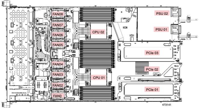
This topic shows the locations of the field-replaceable components and service-related items. The view in the following figure shows the server with the top cover removed.
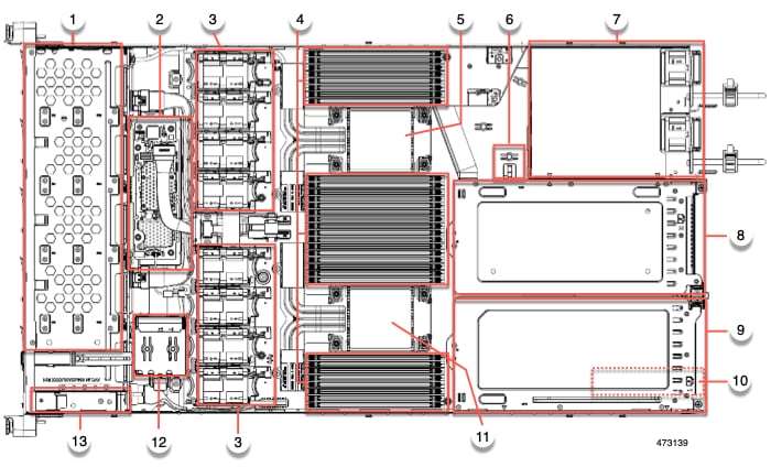
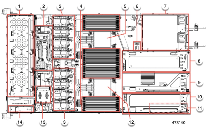
1
Front-loading drive bays 1–10 support SAS/SATA drives.
2
M7 modular RAID card or SATA Interposer card
3
Cooling fan modules, eight.
Each fan is hot-swappable
4
DIMM sockets on motherboard, 32 total, 16 per CPU
Eight DIMM sockets are placed between the CPUs and the server sidewall, and 16 DIMM sockets are placed between the two CPUs.
5
Motherboard CPU socket
CPU2 is the top socket.
6
M.2 module connector
Supports a boot-optimized RAID controller with connectors for up to two SATA M.2 SSDs
7
Power Supply Units (PSUs), two
8
PCIe riser slot 3
Accepts 1 half height, half width PCIe riser card.
9
PCIe riser slot 2
Accepts 1 half height, half width PCIe riser card.
10
PCIe riser slot 1
Accepts 1 half height, half width PCIe riser card
11
Modular LOM (mLOM) or Intel X710 OCP 3.0 card bay on chassis floor (x16 PCIe lane)
The mLOM/OCP card bay sits below PCIe riser slot 1.
12
Motherboard CPU socket
CPU1 is the bottom socket.
13
SuperCap module mounting bracket
The SuperCap module (not shown) that mounts into this location provides RAID write-cache backup.
14
Front Panel Controller board
The view in the following figure shows the individual component locations and numbering, including the HHHL PCIe slots.
The Technical Specifications Sheets for all versions of this server, which include supported component part numbers, are at Cisco UCS Servers Technical Specifications Sheets (scroll down to Technical Specifications).
Replacing SAS/SATA Hard Drives or Solid-State Drives
SAS/SATA Drive Population Guidelines
The server is orderable in two different versions, each with a different front panel/drive-backplane configuration.
- Cisco UCS C220 M7 SAS/SATA—Small form-factor (SFF) drives, with 10-drive backplane. Supports up to 10 2.5-inch SAS/SATA drives.
- Cisco UCS C220 M7 NVMe—SFF drives, with 10-drive backplane. Supports up to 10 2.5-inch NVMe-only SSDs. A maximum of 10 NVMe SSDs is supported only when the Cisco 24G Tri-Mode RAID Controller (UCSC-RAID-HP) is configured in the server.
Drive bay numbering is shown in the following figures.

Observe these drive population guidelines for optimum performance:
- When populating drives, add drives to the lowest-numbered bays first.
- Keep an empty drive blanking tray in any unused bays to ensure proper airflow.
- You can mix SAS/SATA hard drives and SAS/SATA SSDs in the same server. However, you cannot configure a logical volume (virtual drive) that contains a mix of hard drives and SSDs. That is, when you create a logical volume, it must contain all SAS/SATA hard drives or all SAS/SATA SSDs.
Replacing a SAS/SATA Drive
Procedure
Remove the drive that you are replacing or remove a blank drive tray from the bay:
- Press the release button on the face of the drive tray.
- Grasp and open the ejector lever and then pull the drive tray out of the slot.
- If you are replacing an existing drive, remove the four drive-tray screws that secure the drive to the tray and then lift the drive out of the tray.
Install a new drive:
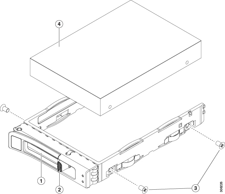
- Place a new drive in the empty drive tray and install the four drive-tray screws.
- With the ejector lever on the drive tray open, insert the drive tray into the empty drive bay.
- Push the tray into the slot until it touches the backplane, and then close the ejector lever to lock the drive in place.
1
3
Drive tray screws (two on each side)
2
4
Drive removed from drive tray
Basic Troubleshooting: Reseating a SAS/SATA Drive
Sometimes it is possible for a false positive UBAD error to occur on SAS/SATA HDDs installed in the server.
- Only drives that are managed by the UCS MegaRAID controller are affected.
- Drives can be affected regardless of where they are installed in the server (front-loaded, rear-loaded, and so on).
- Both SFF and LFF form factor drives can be affected.
- Drives installed in all Cisco UCS C-Series servers with M3 processors and later can be affected.
- Drives can be affected regardless of whether they are configured for hot plug or not.
- The UBAD error is not always terminal, so the drive is not always defective or in need of repair or replacement. However, it is also possible that the error is terminal, and the drive will need replacement.
Before submitting the drive to the RMA process, it is a best practice to reseat the drive. If the false UBAD error exists, reseating the drive can clear it. If successful, reseating the drive reduces inconvenience, cost, and service interruption, and optimizes your server uptime.
Reseat the drive only if a UBAD error occurs. Other errors are transient, and you should not attempt diagnostics and troubleshooting without the assistance of Cisco personnel. Contact Cisco TAC for assistance with other drive errors.
Reseating a SAS/SATA Drive
Sometimes, SAS/SATA drives can throw a false UBAD error, and reseating the drive can clear the error.
Use the following procedure to reseat the drive.
This procedure might require powering down the server. Powering down the server will cause a service interruption.
Before you begin
Before attempting this procedure, be aware of the following:
- Before reseating the drive, it is a best practice to back up any data on it.
- When reseating the drive, make sure to reuse the same drive bay.
- Do not move the drive to a different slot.
- Do not move the drive to a different server.
- If you do not reuse the same slot, the Cisco management software (for example, Cisco IMM) might require a rescan/rediscovery of the server.
Procedure
Attempt a hot reseat of the affected drive(s). Choose the appropriate option:
While the drive is removed, it is a best practice to perform a visual inspection. Check the drive bay to ensure that no dust or debris is present. Also, check the connector on the back of the drive and the connector on the inside of the server for any obstructions or damage.
Also, when reseating the drive, allow 20 seconds between removal and reinsertion.
During boot up, watch the drive's LEDs to verify correct operation.
If the error persists, cold reseat the drive, which requires a server power down. Choose the appropriate option:
- Use your server management software to gracefully power down the server. See the appropriate Cisco management software documentation.
- If server power down through software is not available, you can power down the server by pressing the power button. See Status LEDs and Buttons.
- Reseat the drive as documented in Step 1.
- When the drive is correctly reseated, restart the server, and check the drive LEDs for correct operation as documented in Step 2.
If hot and cold reseating the drive (if necessary) does not clear the UBAD error, choose the appropriate option:
- Contact Cisco Systems for assistance with troubleshooting.
- Begin an RMA of the errored drive.
Replacing a Front-Loading NVMe SSD
This section is for replacing 2.5-inch form-factor NVMe solid-state drives (SSDs) in front-panel drive bays.
Front-Loading NVMe SSD Population Guidelines
The server supports the following front drive bay configurations with 2.5-inch NVMe SSDs:
- UCS C220 M7 with SFF drives, a 10-drive backplane. Drive bay 1 - 10 support 2.5-inch NVMe-only SSDs.
Front-Loading NVME SSD Requirements and Restrictions
Observe these requirements:
- As a best practice, the server should have two CPUs.
- In a single CPU server, Riser 2 is not available depending on the type of risers installed.
- In a single-CPU configuration with 3 HHHL risers, Riser 1 and Riser 2 are direct connected to CPU 1, so for this config Riser 1 and Riser 2 are supported.
- In a single-CPU config with 2 FHFL risers, only Riser 1 is supported.
PCIe riser 2 is not available in a single-CPU system. PCIe riser 2 has connectors for the cable that connects to the front-panel drive backplane.
Observe these restrictions:
- NVMe SFF 2.5-inch SSDs support booting only in UEFI mode. Legacy boot is not supported.
- You cannot control NVMe PCIe SSDs with a SAS RAID controller because NVMe SSDs interface with the server via the PCIe bus.
- UEFI boot is supported in all supported operating systems. Hot-insertion and hot-removal are supported in all supported operating systems except VMWare ESXi.
Replacing a Front-Loading NVMe SSD
This topic describes how to replace 2.5-inch form-factor NVMe SSDs in the front-panel drive bays.
OS-surprise removal is not supported. OS-informed hot-insertion and hot-removal are supported on all supported operating systems except VMware ESXi.
Procedure
Remove an existing front-loading NVMe SSD:
- Shut down the NVMe SSD to initiate an OS-informed removal. Use your operating system interface to shut down the drive, and then observe the drive-tray LED:
- Green—The drive is in use and functioning properly. Do not remove.
- Green, blinking—the driver is unloading following a shutdown command. Do not remove.
- Off—The drive is not in use and can be safely removed.
- Press the release button on the face of the drive tray.
- Grasp and open the ejector lever and then pull the drive tray out of the slot.
- Remove the four drive tray screws that secure the SSD to the tray and then lift the SSD out of the tray.
Install a new front-loading NVMe SSD:
- Place a new SSD in the empty drive tray and install the four drive-tray screws.
- With the ejector lever on the drive tray open, insert the drive tray into the empty drive bay.
- Push the tray into the slot until it touches the backplane, and then close the ejector lever to lock the drive in place.
Observe the drive-tray LED and wait until it returns to solid green before accessing the drive:

- Off—The drive is not in use.
- Green, blinking—the driver is initializing following hot-plug insertion.
- Green—The drive is in use and functioning properly.
1
3
Drive tray screws (two on each side)
2
4
Drive removed from drive tray
Installing a PCIe Cable For Front-Loading NVMe SSDs
The front-loading NVMe SSDs interface with the server via the PCIe bus. Cable CBL-FNVME-C220M7 connects the front-panel drive backplane to the motherboard.
- If the server was ordered with 2.5-inch form-factor NVMe SSDs, this cable was preinstalled at the factory. No action is required.
- If you are adding 2.5-inch form-factor NVMe SSDs for the first time, you must order and install the cable as described in the following procedure.
Procedure
Connect the two connectors on one end of the cable to the PCIE-A1 and PCIE-A2 connectors on the drive backplane.
Route the cables through the chassis cable guides to the rear of the server as shown below.
Connect the single connector on the other end of the cable to the PCIE-FRONT connector on the motherboard.
Replacing Fan Modules
Procedure
Remove an existing fan module:
-
Slide the server out the front of the rack far enough so that you can remove the top cover. You might have to detach cables from the rear panel to provide clearance.
Caution If you cannot safely view and access the component, remove the server from the rack. Install a new fan module:
- Set the new fan module in place. The arrow printed on the top of the fan module should point toward the rear of the server.
- Press down gently on the fan module to fully engage it with the connector on the motherboard.
- Replace the top cover to the server.
- Replace the server in the rack, replace cables, and then fully power on the server by pressing the Power button.
Replacing Riser Cages
The server can support either three half-height PCIe riser cages or two full-height PCIe riser cages in the rear PCIe slots. Cisco offers individual rear risers, which you can order by their PIDs.
If you need to remove the mLOM to install riser cages, see Replacing an mLOM Card.
If you need to remove the OCP card to install riser cages, see Replacing an OCP Card.
Replacing the Same Riser Type
You can replace full-height risers with other full-height risers, or you can replace half-height risers with other half-height risers. To replace the same type of riser, see the following topics:
- Removing Half Height Riser Cages
- Installing Half Height Riser Cages
- Removing Full Height Riser Cages
- Installing Full Height Riser Cages
Switching Between Riser Types
You can change the riser types in your server as needed. If you want to change from HH risers to FH risers, or change from FH risers to HH risers, order the correct PIDs for this riser type change.
You cannot mix riser types in the same server. The server must contain either all full-height risers or all half-height risers.
To switch riser types, see the following topics:
- Removing Half Height Riser Cages
- Installing Full Height Riser Cages
- Removing Full Height Riser Cages
- Installing Half Height Riser Cages
Required Equipment for Replacing Riser Cages
To replace the server's three half-height (HH) rear PCIe riser cages with two full-height (FH) rear PCIe riser cages, you will need to order the appropriate riser cage kits.
Includes riser cage, rear wall, and screws
Includes riser cage, rear wall, and screws
Includes riser cage and screws
Does not include rear wall
To remove and install screws, you also need a #2 Phillips screwdriver, which is not provided by Cisco.
PCIe Riser Options
The Cisco UCS C220 M7 has riser slots 1 through 3 to support different storage options.
Riser 1
- Riser 1A has a 200-pin standard SMT x24 PCIe connector that includes NCSI port and 12V Standby power support. Slot 1 is x16 width, Gen4 PCIe, and supports half-height, ¾ length PCIe cards
- Riser 1B has a 200-pin standard SMT x24 PCIe connector that includes NCSI port and 12V Standby power support. Slot 1 is x16 width, Gen5 PCIe, and supports half-height, ¾ length PCIe cards
- Riser 1C has a 200-pin standard SMT x24 PCIe connector that includes NCSI port and 12V Standby power support. Slot 1 is x16 width, Gen5 PCIe, and supports full-height, ¾ length PCIe cards
Riser 2
- Riser 2A has a 164-pin standard SMT x16 PCIe connector Slot 2 is x16 width, Gen4 PCIe, and supports half-height, ¾ length PCIe cards. This riser is used only in a server that is configured with 3 HHHL slots.
- Riser 2B has a 164-pin standard SMT x24 PCIe connector Slot 1 is x16 width, Gen5 PCIe, and supports half-height, ¾ length PCIe cards
Riser 3
- Riser 3A has a 200-pin standard SMT x24 PCIe MB connector that includes NCSI port and 12V Standby power support. Slot 3 is x16 width, Gen4 PCIe, and supports half-height, ¾ length PCIe cards.
- Riser 3C has a 200-pin standard SMT x24 PCIe MB connector that includes NCSI port and 12V Standby power support. Slot 3 is x16 width, Gen5 PCIe, and supports full-height, ¾ length PCIe cards
Replacing the Same Riser Types
Removing Half Height Riser Cages
This task enables switching from 3 FH rear PCIe cages to 2 HH rear PCIe cages. To complete this procedure, make sure that you have the required equipment. See Required Equipment for Replacing Riser Cages.
Procedure
Remove the server top cover to gain access to the PCIe riser cages.
Remove the three rear PCIe riser cages.

- Locate the riser cages.
- Using a #2 Phillips screwdriver or your fingers, for each riser cage, loosen its captive thumbscrew.
1 Rear Riser Cage 1 2 Rear Riser Cage 2 3 Rear Riser cage 3 4 Riser Cage Thumbscrews, three total (one per riser cage) Using a #2 Phillips screwdriver, remove the four screws that secure the half height rear wall and mLOM/OCP card bracket to the chassis sheet metal.
Remove the half height rear wall and mLOM/OCP card bracket.
Save the three HH riser cages and the half height rear wall.
What to do next
Install the two full-height riser cages. See Installing Full Height Riser Cages.
Installing Half Height Riser Cages
Use this task to install 3 HH rear riser cages after 2 FH rear riser cages are removed.
Procedure
Install the mLOM/OCP card bracket.
Install the half-height rear wall.
Using a #2 Phillips screwdriver, install the four screws that secure the mLOM/OCP card bracket and the half-height rear wall to the server sheet metal.
Tighten screws to 4 lbs-in. Do not over-tighten screws or you risk stripping them!
Install the three half-height riser cages.
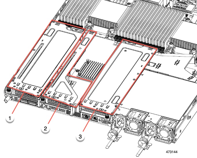
Ensure the three riser cages are securely seated on the motherboard.
Replace the server's top cover.
Removing Full Height Riser Cages
This task enables switching from 2 FH rear PCIe cages to 3 HH rear PCIe cages. To complete this procedure, make sure that you have the required equipment. See Required Equipment for Replacing Riser Cages.
Procedure
Remove the server top cover to gain access to the PCIe riser cages.
Remove the two rear PCIe riser cages.
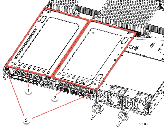
- Locate the riser cages.
- Using a #2 Phillips screwdriver or your fingers, for each riser cage, loosen its captive thumbscrew.
1 Rear Riser Cage 1 2 Rear Riser Cage 2 3 Riser Cage Thumbscrews, two total (one per riser cage) - Using a #2 Phillips screwdriver, remove the four screws that secure the full-height rear wall and mLOM/OCP card bracket to the chassis sheet metal.
Remove the rear wall and mLOM/OCP card bracket.
What to do next
Install the two half-height riser cages. See Installing Half Height Riser Cages .Installing Full Height Riser Cages
Use this task to install 2 FH rear riser cages after 3 HH rear riser cages are removed. Before beginning this procedure, see Required Equipment for Replacing Riser Cages.
Procedure
Using a #2 Phillips screwdriver, install the four screws the secure the mLOM/OCP card bracket and the FH rear wall to the server sheet metal.
Tighten the screws to 4 lbs-in of torque. Do not over-tighten the screws or you risk stripping them.
Install the two full height riser cages.
- Align riser cages 1 and 2 over their PCIe slots, making sure that the captive thumbscrews are aligned with their screw holes.
- Holding each riser cage level, lower it into its PCIe slot, then tighten the thumbscrew by using a #2 Phillips screwdriver or your fingers.
Caution Tighten the screws to 4 lbs-in of torque. Do not over tighten the screws or you risk stripping them. Replace the server's top cover.
Switching Between Full-Height and Half-Height Risers
Removing Half Height Riser Cages
This task enables switching from 3 FH rear PCIe cages to 2 HH rear PCIe cages. To complete this procedure, make sure that you have the required equipment. See Required Equipment for Replacing Riser Cages.
Procedure
Remove the server top cover to gain access to the PCIe riser cages.
Remove the three rear PCIe riser cages.

- Locate the riser cages.
- Using a #2 Phillips screwdriver or your fingers, for each riser cage, loosen its captive thumbscrew.
1 Rear Riser Cage 1 2 Rear Riser Cage 2 3 Rear Riser cage 3 4 Riser Cage Thumbscrews, three total (one per riser cage) Using a #2 Phillips screwdriver, remove the four screws that secure the half height rear wall and mLOM/OCP card bracket to the chassis sheet metal.
Remove the half height rear wall and mLOM/OCP card bracket.
Save the three HH riser cages and the half height rear wall.
What to do next
Install the two full-height riser cages. See Installing Full Height Riser Cages.
Installing Full Height Riser Cages
Use this task to install 2 FH rear riser cages after 3 HH rear riser cages are removed.
Procedure
Install the mLOM/OCP card bracket.
Install the full-height rear wall.
Using a #2 Phillips screwdriver, install the four screws the secure the mLOM/OCP card bracket and the FH rear wall to the server sheet metal.
Tighten the screws to 4 lbs-in of torque. Do not over-tighten the screws or you risk stripping them.
Install the two full height riser cages.
- Align riser cages 1 and 2 over their PCIe slots, making sure that the captive thumbscrews are aligned with their screw holes.
- Holding each riser cage level, lower it into its PCIe slot, then tighten the thumbscrew by using a #2 Phillips screwdriver or your fingers.
Caution Tighten the screws to 4 lbs-in of torque. Do not over tighten the screws or you risk stripping them. Replace the server's top cover.
Removing Full Height Riser Cages
This task enables switching from 2 FH rear PCIe cages to 3 HH rear PCIe cages. To complete this procedure, make sure that you have the required equipment. See Required Equipment for Replacing Riser Cages.
Procedure
Remove the server top cover to gain access to the PCIe riser cages.
Remove the two rear PCIe riser cages.

- Locate the riser cages.
- Using a #2 Phillips screwdriver or your fingers, for each riser cage, loosen its captive thumbscrew.
1 Rear Riser Cage 1 2 Rear Riser Cage 2 3 Riser Cage Thumbscrews, two total (one per riser cage) - Using a #2 Phillips screwdriver, remove the four screws that secure the full-height rear wall and mLOM/OCP card bracket to the chassis sheet metal.
Remove the rear wall and mLOM/OCP card bracket.
Grasp each end of the full height rear wall and remove it.
Save the FH riser cages and the full height rear wall.
What to do next
Install the two half-height riser cages. See Installing Half Height Riser Cages .
Installing Half Height Riser Cages
Use this task to install 3 HH rear riser cages after 2 FH rear riser cages are removed.
Procedure
Install the mLOM/OCP card bracket.
Install the half-height rear wall.
Using a #2 Phillips screwdriver, install the four screws that secure the mLOM/OCP card bracket and the half-height rear wall to the server sheet metal.
Tighten screws to 4 lbs-in. Do not over-tighten screws or you risk stripping them!
Install the three half-height riser cages.

Ensure the three riser cages are securely seated on the motherboard.
Replace the server's top cover.
Replacing CPUs and Heatsinks
This section contains CPU configuration rules and the procedure for replacing CPUs and heatsinks:
CPU Configuration Rules
This server has two CPU sockets on the motherboard. Each CPU supports eight DIMM channels (16 DIMM slots). See DIMM Slot Numbering.
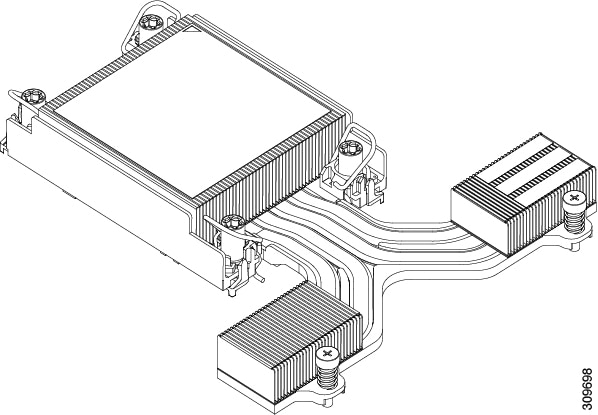
- The server can be configured with either Intel Xeon Fourth Generation Xeon Scalable Processors or Intel Fifth Generation Xeon Scalable Processors. If your server is configured with, or if you will be upgrading to, Intel Fifth Generation Xeon Scalable Processors, an airflow baffle is required for optimal airflow (UCSC-AD-C220M7=). The baffle is orderable through Cisco.
- The server can operate with one CPU or two identical CPUs installed.
- The minimum configuration is that the server must have at least CPU 1 installed. Install CPU 1 first, and then CPU 2.
- The following restrictions apply when using a single-CPU configuration:
- Any unused CPU socket must have the protective dust cover from the factory in place.
- The maximum number of DIMMs is 16 (only CPU 1 channels A, B, C, D, E, F, G, and H).
- In a single CPU server, up to 2HHHL or 1FHFL riser are supported. Riser 3 is not available.
- Front-loading NVME drives are unavailable (they require CPU 2).
- One type of CPU heatsink is available for this server, the low profile heatsink (UCSC-HSLP-C220M7). This heatsink has four T30 Torx screws on the main heatsink, and 2 Phillips-head screws on the extended heatsink.
Tools Required For CPU Replacement
CPU Upgrade
If you are upgrading from Intel Fourth Generation Xeon Processors to Intel Fifth Generation Xeon Processors, a new air baffle is required to ensure optimal airflow. To upgrade the CPUs, you must order the baffle separately (UCSC-AD-C220M7=) and replace the existing baffle with the new one (UCSC-AD-C220M7=).
However, if you will continue to use Intel Fourth Generation Xeon Processorss, you do not need to order the new airflow baffle. You must use the existing airflow baffle.
To upgrade the server's CPU(s), you also need the standard set of tools in CPU Replacement below.
CPU Replacement
For all CPU replacement, installation, or upgrades, the following tools are required:
- T-30 Torx driver—Supplied with replacement CPU.
- #1 flat-head screwdriver—Supplied with replacement CPU.
- #2 Phillips screwdriver.
- CPU assembly tool—Supplied with replacement CPU. Orderable separately as Cisco PID UCS-CPUAT=.
- Heatsink cleaning kit—Supplied with replacement CPU. Orderable separately as Cisco PID UCSX-HSCK=. One cleaning kit can clean up to four CPUs.
- Thermal interface material (TIM)—Syringe supplied with replacement CPU. Use only if you are reusing your existing heatsink (new heatsinks have a pre-applied pad of TIM). Orderable separately as Cisco PID UCS-CPU-TIM=. One TIM kit covers one CPU.
Removing CPUs and Heat Sinks
Use the following procedure to remove an installed CPU and heatsink from the server. With this procedure, you will remove the CPU from the motherboard, disassemble individual components, then place the CPU and heatsink into the fixture that came with the CPU.
Procedure
Remove any airflow baffle to expose the components.
Detach the CPU and heatsink (the CPU assembly) from the CPU socket.
- Using a #2 Phillips screwdriver, loosen the two captive screws at the far end of the heatsink.
- Using a T30 Torx driver, loosen all the securing nuts.
- Push the rotating wires towards each other to move them to the unlocked position. The rotating wire locked and unlocked positions are labeled on the top of the heatsink.
Caution Make sure that the rotating wires are as far inward as possible. When fully unlocked, the bottom of the rotating wire disengages and allows the removal of the CPU assembly. If the rotating wires are not fully in the unlocked position, you can feel resistance when attempting to remove the CPU assembly. Caution While lifting the CPU assembly, make sure not to bend the heatsink fins. Also, if you feel any resistance when lifting the CPU assembly, verify that the rotating wires are completely in the unlocked position. Put the CPU assembly on a rubberized mat or other ESD-safe work surface.
When placing the CPU on the work surface, the heatsink label should be facing up. Do not rotate the CPU assembly upside down.
Ensure that the heatsink sits level on the work surface.
Attach a CPU dust cover to the CPU socket.
- Align the posts on the CPU bolstering plate with the cutouts at the corners of the dust cover.
- Lower the dust cover and simultaneously press down on the edges until it snaps into place over the CPU socket.
Caution Do not press down in the center of the dust cover! Detach the CPU from the CPU carrier.
- Turn the CPU assembly upside down, so that the heatsink is pointing down. This step enables access to the CPU securing clips.
- Gently lift the TIM breaker (1 in the following illustration) in a 90-degree upward arc to partially disengage the CPU clips on this end of the CPU carrier.
- Lower the TIM breaker into the u-shaped securing clip to allow easier access to the CPU carrier.
Note Make sure that the TIM breaker is completely seated in the securing clip. Caution Be careful when flexing the CPU carrier! If you apply too much force you can damage the CPU carrier. Flex the carrier only enough to release the CPU clips. Make sure to watch the clips while performing this step so that you can see when they disengage from the CPU carrier. When all the CPU clips are disengaged, grasp the carrier, and lift it and the CPU to detach them from the heatsink.
If the carrier and CPU do not lift off of the heatsink, attempt to disengage the CPU clips again.
Use the provided cleaning kit (UCSX-HSCK) to remove all of the thermal interface barrier (thermal grease) from the CPU, CPU carrier, and heatsink.
Make sure to use only the Cisco-provided cleaning kit, and make sure that no thermal grease is left on any surfaces, corners, or crevices. The CPU, CPU carrier, and heatsink must be completely clean.
Transfer the CPU and carrier to the fixture.
- Flip the CPU and carrier right-side up.
- Align the CPU and carrier with the fixture.
- Lower the CPU and CPU carrier onto the fixture.
What to do next
Choose the appropriate option:
- If you will be installing a CPU, go to Installing the CPUs and Heatsinks.
- If you will not be installing a CPU, verify that a CPU socket cover is installed. This option is valid only for CPU socket 2 because CPU socket 1 must always be populated in a runtime deployment.
Installing the CPUs and Heatsinks
Use this procedure to install a CPU if you have removed one, or if you are installing a CPU in an empty CPU socket. To install the CPU, you will move the CPU to the fixture, then attach the CPU assembly to the CPU socket on the server mother board.
Procedure
Remove the CPU socket dust cover on the server motherboard.
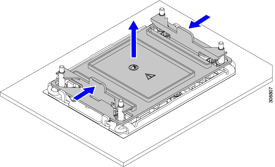
- Push the two vertical tabs inward to disengage the dust cover.
- While holding the tabs in, lift the dust cover up to remove it.
- Store the dust cover for future use.
Caution Do not leave an empty CPU socket uncovered. If a CPU socket does not contain a CPU, you must install a CPU dust cover. Grasp the CPU fixture on the edges labeled PRESS, lift it out of the tray, and place the CPU assembly on an ESD-safe work surface.
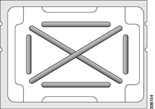
- If you are installing a new heatsink, it is shipped with a pre-applied pad of TIM. Go to step 4.
- If you are reusing a heatsink, you must remove the old TIM from the heatsink and then apply new TIM to the CPU surface from the supplied syringe. Continue with step a below.
- Apply the Bottle #1 cleaning solution that is included with the heatsink cleaning kit (UCSX-HSCK=), as well as the spare CPU package, to the old TIM on the heatsink and let it soak for a least 15 seconds.
- Wipe all of the TIM off the heatsink using the soft cloth that is included with the heatsink cleaning kit. Be careful to avoid scratching the heatsink surface.
- Completely clean the bottom surface of the heatsink using Bottle #2 to prepare the heatsink for installation.
- Using the syringe of TIM provided with the new CPU (UCS-CPU-TIM=), apply 1.5 cubic centimeters (1.5 ml) of thermal interface material to the top of the CPU. Use the pattern shown in the following figure to ensure even coverage.
Caution Use only the correct heatsink for your CPU (UCSC-HSLP-C220M7). Attach the heatsink to the socket.
- Align the CPU and heatsink.
- Lower the heatsink onto the CPU.
- Close the rotating wires to lock the heatsink into place on the TIM grease.
Install the CPU to the motherboard.
For servers that have Intel Fifth Generation Xeon Scalable Processors, install the new air duct (UCSC-AD-C220M7=).
Additional CPU-Related Parts to Order with RMA Replacement CPUs
When a return material authorization (RMA) of the CPU is done on a Cisco UCS C-Series server, additional parts might not be included with the CPU spare. The TAC engineer might need to add the additional parts to the RMA to help ensure a successful replacement.
The following items apply to CPU replacement scenarios. If you are replacing a system chassis and moving existing CPUs to the new motherboard, you do not have to separate the heatsink from the CPU.
- Scenario 1—You are reusing the existing heatsinks:
- Heatsink cleaning kit (UCSX-HSCK=) One cleaning kit can clean up to four CPUs.
- Thermal interface material (TIM) kit for M7 servers (UCS-CPU-TIM=) One TIM kit covers one CPU.
- Heatsink: UCSC-HSLP-C220M7 New heatsinks have a pre-applied pad of TIM.
- Heatsink cleaning kit (UCSX-HSCK=) One cleaning kit can clean up to four CPUs.
- CPU Carrier
- #1 flat-head screwdriver (for separating the CPU from the heatsink)
- Heatsink cleaning kit (UCSX-HSCK=) One cleaning kit can clean up to four CPUs.
- Thermal interface material (TIM) kit (UCS-CPU-TIM=) One TIM kit covers one CPU.
A CPU heatsink cleaning kit is good for up to four CPU and heatsink cleanings. The cleaning kit contains two bottles of solution, one to clean the CPU and heatsink of old TIM and the other to prepare the surface of the heatsink.
New heatsink spares come with a pre-applied pad of TIM. It is important to clean any old TIM off of the CPU surface prior to installing the heatsinks. Therefore, even when you are ordering new heatsinks, you must order the heatsink cleaning kit.
Upgrading to Intel Xeon Fifth Generation Scalable Server Processors
Use this task to uprade to Intel Fifth Generation Scalable Server processors.
Before you begin
To upgrade CPUs, you will need to power off the server, so be aware that this task will cause a service interruption.
Also, you will need some tools to perform this task. See Tools Required For CPU Replacement.
Procedure
If you have not done so already, review the CPU Configuration Rules.
Remove the server's top cover.
Remove the air duct.
Remove the existing Intel Xeon Fourth Generation Scalable Processor(s).
Store the removed CPUs in an ESD-safe bag.
Install the new Intel Xeon Fifth Generation Scalable Processor(s).
Replace the air duct.
Replace the server's top cover.
Reapply power and return the server to operation.
Replacing Memory DIMMs
DIMMs and their sockets are fragile and must be handled with care to avoid damage during installation.
DIMMs and their slots are keyed to insert only one way. Make sure to align the notch on the bottom of the DIMM with the key in the DIMM slot. If you are seating a DIMM in a slot and feel resistance, remove the DIMM and verify that its notch is properly aligned with the slot's key.
Cisco does not support third-party DIMMs. Using non-Cisco DIMMs in the server might result in system problems or damage to the motherboard.
To ensure the best server performance, it is important that you are familiar with memory performance guidelines and population rules before you install or replace DIMMs.
DIMM Population Rules and Memory Performance Guidelines
The following sections provide partial information for memory usage. mixing, and population guidelines. For detailed information about memory usage and population, download the PDF of the Cisco UCS/UCSX M7 Memory Guide.
DIMMs Supported By Intel Fourth Generation Xeon Scalable Server Processors
The following table shows the DIMMs supported by Intel Fourth Generation Xeon Scalale Server Processors.
16GB DDR5-4800 RDIMM 1Rx8 (16 Gb)
32GB DDR5-4800 RDIMM 1Rx4 (16 Gb)
64GB DDR5-4800 RDIMM 2Rx4 (16 Gb)
128GB DDR5-4800 RDIMM 4Rx4 (16 Gb)
DIMMs Supported By Intel Fifth Generation Xeon Scalable Server Processors
The following table shows the DIMMs supported by Intel Fifth Generation Xeon Scalale Server Processors.
16GB DDR5-5600 RDIMM 1Rx8 (16 Gb)
32GB DDR5-5600 RDIMM 1Rx4 (16 Gb)
64GB DDR5-5600 RDIMM 2Rx4 (16 Gb)
96GB DDR5-5600 RDIMM 2Rx4 (24 Gb)
128GB DDR5-5600 RDIMM 4Rx4 (16 Gb)
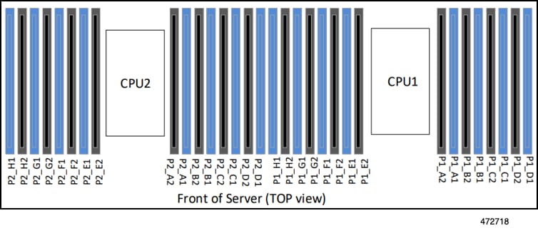
DIMM Slot Numbering
The following figure shows the numbering of the DIMM slots on the motherboard.
DIMM Population Rules
Observe the following guidelines when installing or replacing DIMMs for maximum performance:
- The Cisco UCS C220 M7 supports DIMMs (RDIMMs).
- Each CPU supports eight memory channels, A through H.
- CPU 1 supports channels P1 A1, P1 A2, P1 B1, P1 B2, P1 C1, P1 C2, P1 D1, P1 D2, P1 E1, P1 E2, P1 F1, P1 F2, P1 G1, P1 G2, P1 H1, and P1 H2.
- CPU 2 supports channels P2 A1, P2 A2, P2 B1, P2 B2, P2 C1, P2 C2, P2 D1, P2 D2, P2 E1, P2 E2, P2 F1, P2 F2, P2 G1, P2 G2, P2 H1, and P2 H2.
NoteThe section below lists recommended configurations. Using 5, 7, 9, 10, or 11 DIMMs per CPU is not recommended. - All DDR5 DIMM must be in the same speed per processor socket or the processor will run at the lowest DIMM/CPU speed
- x8 DIMMs and x4 DIMMS cannot be mixed in the same channel or same processor socket
- Mixing DIMMs from different vendors is allowed for RDIMMs, but not for 3DS RDIMM.
Memory Population Order
The Cisco UCS C220 M7 server has two memory options, DIMMs only or DIMMs plus Intel Optane PMem 200 series memory.
Memory slots are color-coded, blue and black. The color-coded channel population order is blue slots first, then black. DIMMs for CPU 1 and CPU 2 (when populated) must always be configured identically.
The following tables show the memory population order for each memory option.
Number of DDR5 DIMMs per CPU (Recommended Configurations)
Populate CPU 1 Slot
Populate CPU2 Slots
P1 Blue #1 Slots
P1 Black #2 Slots
P2 Blue #1 Slots
P2 Black #2 Slots